The Commercial Arrival of SAE J2954 Wireless Charging
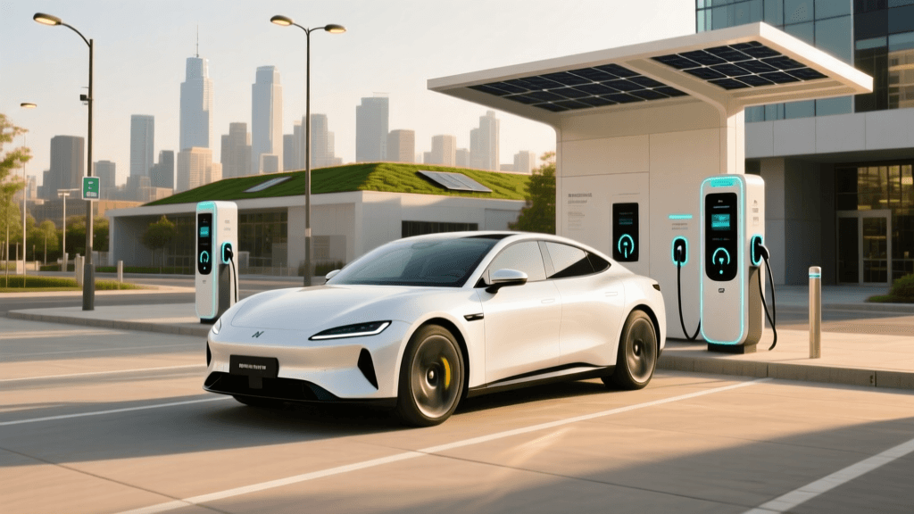
The electric vehicle industry has long anticipated the day when plugging in would become obsolete. With the commercial launch of SAE J2954-compliant wireless charging systems, spearheaded by companies like WiTricity and their Halo platform, that future is now a reality for select fleets and premium consumer setups. Unlike early inductive prototypes, modern magnetic resonance technology offers high efficiency and practical ground clearances. However, as these systems move from the laboratory to real-world driveways and commercial depots, facility managers and EV owners are encountering a new set of troubleshooting challenges.
While a physical cable provides a direct, unmistakable connection, wireless power transfer relies on precise electromagnetic coupling, high-frequency inverters, and complex sensor arrays. When a wireless charging session fails to initiate or suffers from severe efficiency drops, diagnosing the root cause requires a different mindset than traditional Level 2 troubleshooting. In this guide, we break down the most common issues associated with commercial SAE J2954 wireless EV charging systems and provide actionable problem-solving steps.
Understanding Magnetic Resonance and the 85 kHz Standard
Before troubleshooting, it is vital to understand the underlying physics. The SAE International J2954 Standard establishes the framework for light-duty wireless charging, mandating an operating frequency of 85 kHz. Systems like the WiTricity Halo use magnetic resonance rather than simple induction. Both the ground pad (transmitter) and the vehicle pad (receiver) contain tuned capacitor-coil circuits. When they are tuned to the same resonant frequency, energy transfers efficiently across the air gap, even with lateral misalignment or varying Z-axis (ground clearance) distances.
Because the system relies on resonance, any factor that alters the inductance or capacitance of the coils—or disrupts the communication handshake between the pads—will trigger a fault code and halt the charge.
Top Troubleshooting Scenarios for Wireless EV Chargers
1. Ground Pad to Vehicle Pad Misalignment
The Problem: The vehicle is parked over the pad, but the system refuses to initiate charging, or the efficiency drops below 85%, generating excess heat.
The Diagnosis: SAE J2954 defines specific alignment tolerances. While magnetic resonance is forgiving, extreme lateral (X/Y axis) or rotational misalignment will decouple the magnetic fields. Furthermore, if a vehicle's suspension is heavily loaded (altering the Z-axis gap beyond the certified 100mm to 250mm range), the coupling coefficient drops drastically.
The Solution:
- Verify Sensor Calibration: Most commercial systems use optical, magnetic, or RFID-based alignment assists. Check the dashboard UI or fleet management software to ensure the alignment sensors are not obstructed by mud, snow, or ice.
- Check Suspension Load: If the vehicle is heavily laden with cargo, the air gap may exceed the maximum threshold. Unload the vehicle or adjust the air suspension to the predefined charging height setting.
- Inspect Ground Pad Leveling: Over time, concrete settling can cause the embedded ground pad to tilt. Use a digital level to ensure the pad is perfectly flush with the surrounding surface. A tilt greater than 2 degrees can severely impact the magnetic flux path.
2. Foreign Object Debris (FOD) and Living Object Protection (LOP) False Positives
The Problem: The charging session initiates but aborts within seconds, accompanied by an FOD or LOP warning on the user interface.
The Diagnosis: To prevent metal objects from heating up (FOD) or living creatures from being exposed to electromagnetic fields (LOP), wireless pads are equipped with radar, thermal, and capacitive sensors. In outdoor environments, these sensors are highly prone to false positives.
The Solution:
- Clear Metallic Debris: Even a small metallic candy wrapper, a stray bolt, or a wet metallic leaf can trigger the FOD sensor by absorbing magnetic flux and heating up. Sweep the pad surface with a non-metallic brush.
- Recalibrate Capacitive LOP Sensors: Heavy rain, standing water, or thick snow accumulation on the ground pad can alter the capacitive field, tricking the system into thinking a living organism is present. If weather conditions are severe, utilize the system manual override or weather mode if provided by the OEM, or clear the standing water using a rubber squeegee.
- Check for Radar Obstructions: Some advanced pads use millimeter-wave radar for LOP. Ensure the small radar domes on the perimeter of the pad are free of caked mud or ice.
3. Communication Handshake and Pairing Failures
The Problem: The vehicle is perfectly aligned, the pads are clear of debris, but the ground station and vehicle cannot negotiate the power transfer protocol.
The Diagnosis: According to guidelines researched by the National Renewable Energy Laboratory (NREL), wireless systems require a low-power communication channel (often Wi-Fi, Bluetooth, or PLC via a secondary low-power coil) to negotiate power levels and safety checks before high-power transfer begins. Signal interference in crowded commercial depots can block this handshake.
The Solution:
- Eliminate RF Interference: In fleet depots, heavy machinery, high-voltage switchgear, and dense Wi-Fi networks can drown out the pairing signal. Temporarily power down nearby non-essential RF emitters to test if the handshake completes.
- Reboot the Ground Station Controller: Just like a Level 2 networked charger, the wireless base station has an internal computer. Perform a hard reset at the breaker panel to clear cached communication errors.
- Update Firmware: Ensure both the vehicle onboard wireless receiver and the ground pad transmitter are running the latest firmware. Mismatched SAE J2954 protocol versions will cause an immediate handshake rejection.
SAE J2954 vs. Traditional Level 2: Troubleshooting Matrix
When transitioning from traditional plug-in infrastructure to wireless systems, technicians must adapt their diagnostic workflows. The table below contrasts the primary failure points and diagnostic tools required for each technology.
| Diagnostic Metric | Traditional Level 2 (J1772 / CCS1) | Wireless SAE J2954 (Magnetic Resonance) |
|---|---|---|
| Primary Connection Failure | Damaged pins, worn receptacles, locking pin failure. | X/Y axis misalignment, Z-axis air gap exceeding tolerance. |
| Safety Interlocks | Proximity pilot (CP) and control pilot (PP) voltage checks. | FOD thermal sensors, LOP capacitive/radar arrays. |
| Communication Protocol | PWM signaling over Control Pilot wire, PLC for DC Fast. | Wireless RF (Wi-Fi/BLE) or low-power inductive coupling. |
| Environmental Vulnerability | Connector icing, salt corrosion on pins. | Metallic debris on pad, standing water altering capacitance. |
| Required Test Equipment | Multimeter, EVSE simulator, oscilloscope. | Gauss meter, RF spectrum analyzer, digital level. |
Preventative Maintenance for Wireless Charging Infrastructure
Troubleshooting is best avoided through rigorous preventative maintenance. While wireless chargers eliminate the physical wear and tear associated with heavy charging cables and fragile connectors, the ground pad requires specific upkeep to maintain WiTricity Halo Technology efficiency standards.
- Routine Surface Inspections: Sweep the pad area daily in commercial environments. Unlike a plugged-in cable that hangs above the ground, wireless pads sit flush and are prone to collecting metallic dust, discarded foil wrappers, and gravel.
- Epoxy and Sealant Checks: The ground pad is typically encased in a high-strength polymer or epoxy. Inspect the casing quarterly for micro-fractures. Water ingress into the transmitter coil housing will cause catastrophic capacitor failure and ground faults.
- Thermal Imaging Audits: Once a year, use a thermal imaging camera to scan the ground pad during an active charge cycle. Hotspots on the pad surface may indicate internal coil degradation, failing ferrite tiles, or localized FOD sensor blindness.
The Future of Wireless EV Charging Diagnostics
As commercial wireless EV charging scales, we expect OEMs to integrate more sophisticated onboard diagnostics (OBD) specifically for the receiver pad. Future iterations of the SAE J2954 standard will likely mandate more granular telemetry, allowing fleet managers to see real-time coupling coefficients and localized pad temperatures via cloud dashboards. Until then, mastering the intersection of electromagnetic theory, RF communication, and environmental awareness is the key to keeping wireless EV fleets powered and on the road.